Print files on MakerWorld → Download as PDF
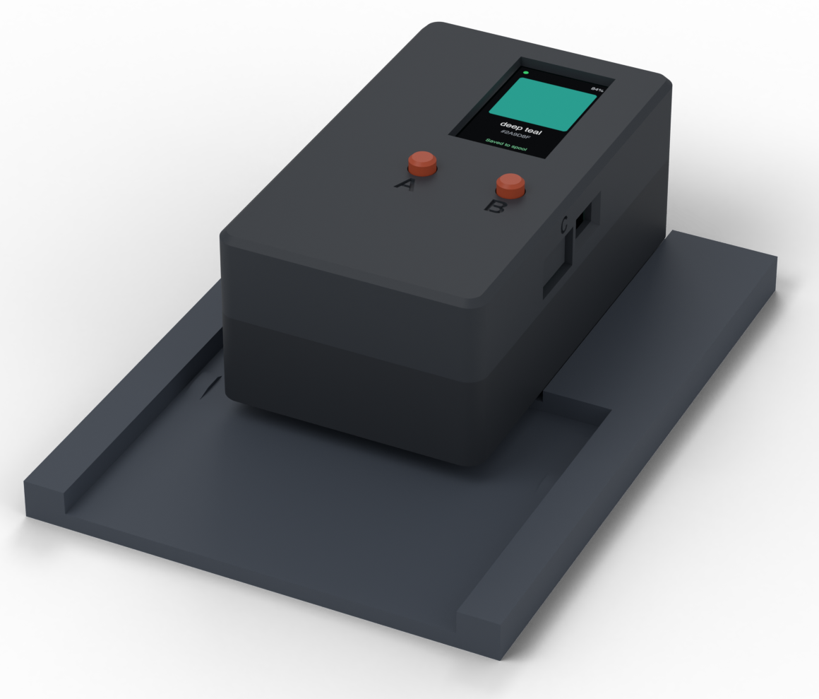
A pocket color reader for 3D-printing filament: an AS7341 spectral sensor and a Seeed XIAO ESP32-S3 display in a 3D-printed case. Works on its own, or with a free 3D Spool Tracker account.
Electronics
| Part | Qty | Notes |
|---|---|---|
| Seeed 1.14″ IPS display with XIAO ESP32-S3 Plus | 1 | The whole reader is built around this board. Other displays won't fit. |
| Waveshare AS7341 spectral color sensor | 1 | Its 6-pin connector gets removed and 4 wires soldered on. |
| LiPo battery, 150 mAh, about 32 × 17.5 × 4.3 mm, 2-pin JST plug | 1 | Its plug's two wires need swapping before it goes in (step 4). |
| Pre-crimped 4-pin cable that fits the display board's Grove port (the JY kit) | 1 | Cut to length: the plug end goes into the display board, the cut end is soldered to the sensor. |
Hardware
Where to get the screws: screw set.
| Part | Qty | Where |
|---|---|---|
| M2 × 4 screw | 2 | Sensor board into the body (4 mm is the maximum length). |
| M3 × 16 screw | 4 | Body → carrier → housing, from underneath. |
| M3 heat-set insert (for a 4.0 mm hole, up to 5.7 mm long) | 2 | Underside of the body, for the tray. |
| M3 × 8 screw | 2 | Swatch or strand tray to the body (through the probe plate when it's stacked on the tray). |
| M3 countersunk screw, 6–8 mm | 2 | Probe plate on its own, for Probe mode. |
Tools
Soldering iron and solder, desoldering braid or pump (or hot air), wire strippers, a multimeter, a small screwdriver set, and a heat-set insert tip for the iron.
Printed parts
Print everything in opaque, matte black or charcoal. Light that leaks through or bounces off a light-colored case changes the readings. The parts are already oriented for printing in the 3MF, on MakerWorld.
| Part | Qty | Notes |
|---|---|---|
| Body (with the built-in nose) | 1 | Print on a smooth plate: the nose face touches what you scan. |
| Carrier | 1 | |
| Housing | 1 | Optional: the A/B/C label inlay, printed in a second color. |
| Button caps | 2 | |
| Swatch tray | 1 | For printed swatches. |
| Strand tray | 1 | For a piece of filament. |
| Probe plate | 1 | For pressing the nose onto printed parts. |
| Reference swatches | 1 each | Bambu Lab PLA Matte Ivory White and Charcoal, hanging-tag swatch model. These two exact filaments: their colors are built into the firmware. |
| Probe calibration plaques (25 × 25 × 5 mm) | 1 each | Same two filaments, only needed if you use Probe mode. Scan the top face, with the nose centered and the reader held level. |
As an Amazon Associate, 3D Spool Tracker earns from qualifying purchases. Product links on this page may include affiliate tags. Prices are the same whether you use our links or not.
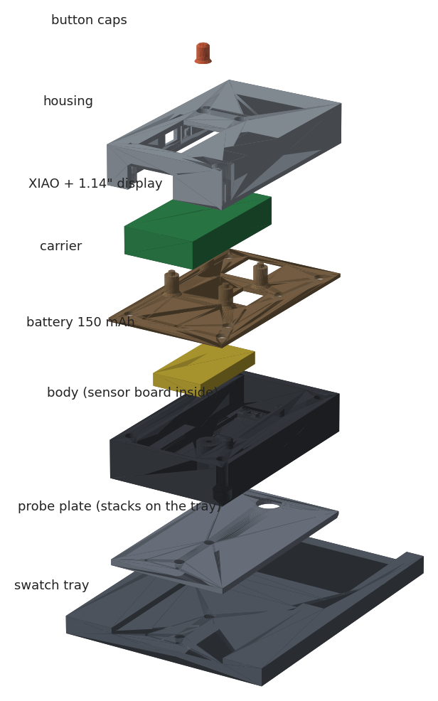
- Remove the 6-pin connector from the AS7341 board. It's too tall for the case. Desolder it, or clip the plastic off and remove the pins one at a time. Clean the pads with braid.
- Cut the pre-crimped cable 6–7 cm from its plug and strip the cut ends.
- Work out which wire is which. Hold the plug next to the display board's Grove port and note which wire lands on VCC, GND, SDA and SCL in the labels printed beside it. Don't go by wire color alone; it varies between cables.
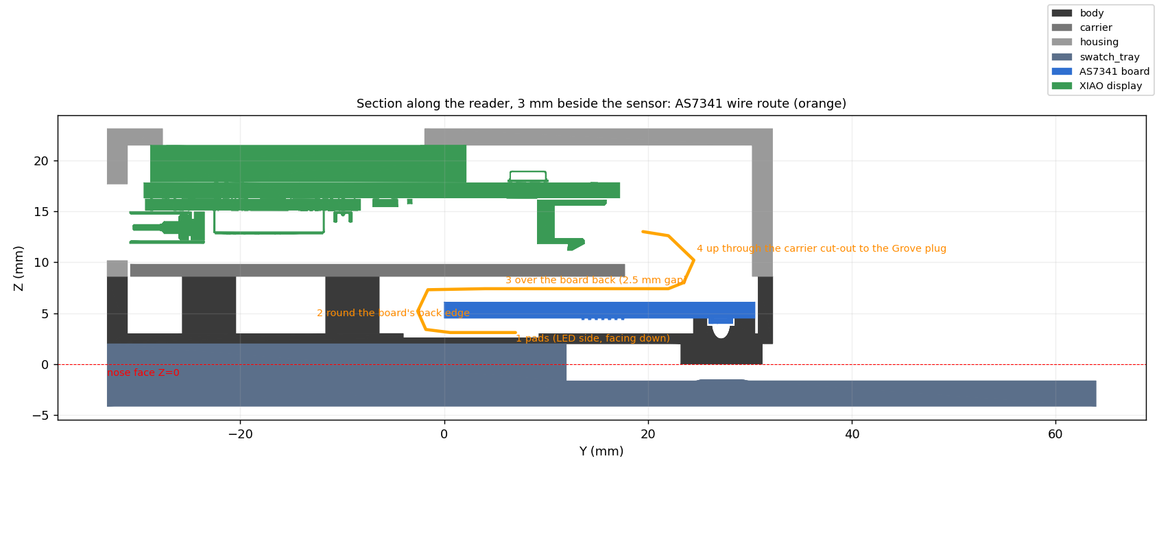
- Solder each wire to the sensor pad with the same name (VCC, GND, SDA, SCL), on the same side as the sensor and LEDs. Leave INT and GPIO empty. That side faces down in the case, so keep the joints low and flat.
- Check every wire with a multimeter, pad to plug pin, and check that no two neighbors are shorted.
- Press the two M3 heat-set inserts into the holes on the underside of the body with the soldering iron. Keep them straight and flush.
- Check the two alignment pin holes in the carrier and housing. If the pins on top of the body won't go in, open the holes up slightly with a 3.5 mm drill bit, turned by hand.
- Fit the sensor board into the body, sensor and LEDs facing down into the pockets above the nose, and fix it with the two M2 × 4 screws. Don't overtighten. Route the wires round the board's back edge as in the section above.
- Swap the two wires in the battery's plug. This battery's plug is wired the opposite way to the display board's socket. Lift each terminal's small latch with a pin or needle, slide it out, and push it back in the other position until it clicks. Do one wire at a time so the bare terminals can't touch.
- Check the polarity before plugging in. The red wire must go to the + pin of the display board's battery socket. Plugging it in backwards can damage the board.
Never flip the power switch with metal tweezers or a screwdriver. The switch's metal shell is connected to ground, and touching it and a pin at the same time shorts the battery. Use a plastic tool or a fingernail.
- Slide the battery onto its shelf in the body, above the sensor board, leads toward the carrier's battery opening.
- Put the carrier on the body over the alignment pins. Bring the sensor wires and the battery leads up through the carrier's openings. The battery opening is large enough to pass the battery through if that's easier.
- Drop the two button caps into the housing (A and B holes), then place the display board in the housing, screen to the window and USB-C to its opening. (Fitting it onto the carrier's posts first works too.)
- Plug in the sensor's Grove plug and the battery on the display board.
- Bring the housing down onto the carrier over the alignment pins. Check that no wire is pinched and that the buttons click.
- Screw it together from underneath with the four M3 × 16 screws.
- Fit the swatch tray with the two M3 × 8 screws. For Probe mode, take the tray off and fit the probe plate with the two countersunk screws instead. The probe plate can also stay on stacked under the swatch tray: the M3 × 8 screws go through both.
The two small holes in the underside line up with the XIAO's B (boot) and R (reset) buttons. If the board ever stops showing up on USB, hold B with a straightened paperclip while plugging in. You don't need to open the case.
- On a computer with Chrome or Edge, open the flasher, plug the reader in with a USB-C data cable, and click Install.
- On first start the reader offers WiFi setup. Scan the QR code with your phone (or join
ColorInspector-Setup-xxxx), choose your WiFi, and optionally paste an API key from your 3D Spool Tracker account. Or tap C to stay offline. Both work. To set up WiFi later, tap C for Info, then tap B for Network, then tap A (or hold A while switching the reader on).
- On the home screen, long press B. Insert the Ivory White swatch and tap B. Follow the prompts.
- Insert the Charcoal swatch and tap B.
- Scan a few swatches (tap A). Two scans of the same swatch should land within about 0.5 ΔE.
- Any time later, check it: long press B, insert white and tap C, then charcoal and tap C. “Calibration OK” means nothing to do.
Each mode (Swatch, Strand, Probe) has its own calibration. Calibrate the modes you use, with the references in the same form: swatches in the swatch tray, filament in the strand tray, and for Probe mode the two calibration plaques with the probe plate fitted.
| Button | Home screen |
|---|---|
| A | Tap: scan · long press: compare two samples |
| B | Tap: next mode (Swatch → Strand → Probe) · long press: calibrate or check |
| C | Info screen · on Info, B opens Network: WiFi setup, the reader's web page (QR code), updates |
Every scan is kept on the reader (the last 300). Open its web page from the Network screen to name, compare or download them. Full help: Color Inspector help.